
High-Performance Rear Differential Mounting & Chain Tensioner


Both rear differential mounts withstand the motor’s pulling load and the differential’s vibration during operation.


Rear diff mounts assembled to chassis
1. Project Scope & Challenge
Objective: Design a lightweight, high-stiffness mounting assembly for the vehicle's rear differential, capable of transmitting $240$ Nm of motor torque while integrating a precise mechanism for chain tensioning.
Role: Mechanical Design Engineer & FEA Lead
Tools: SolidWorks, ANSYS Mechanical, Hand Calculation, GD&T.
2. Analytical Modeling & Load Derivation (First Principles)
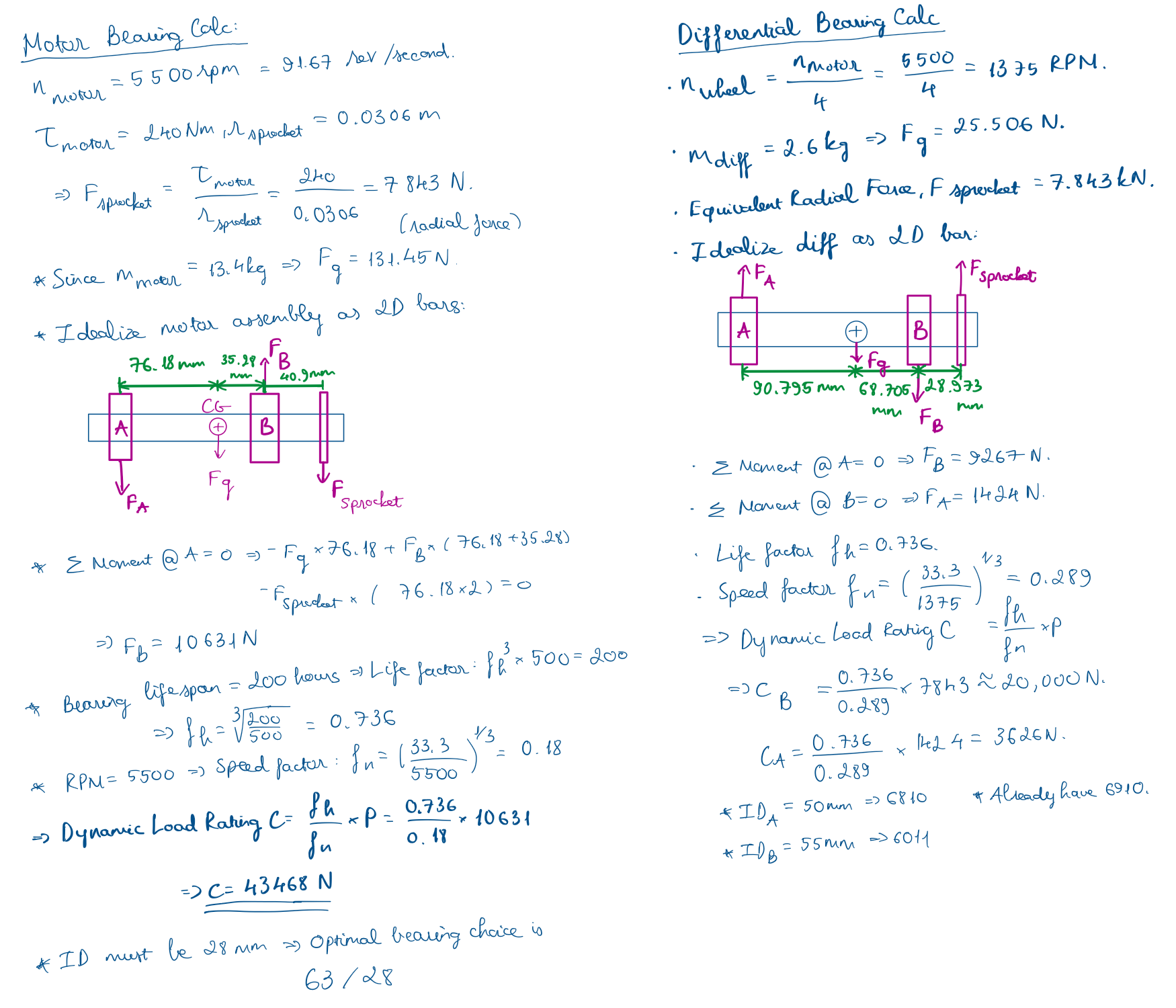
Before beginning CAD geometry, I performed static analysis to determine the governing loads. Ideally, the differential assembly behaves as a rotating shaft subjected to immense radial loads from the chain drive.
Torque Conversion: Calculated the wheel torque and chain tension based on a 5500 RPM motor input and the specific gear reduction ratio.
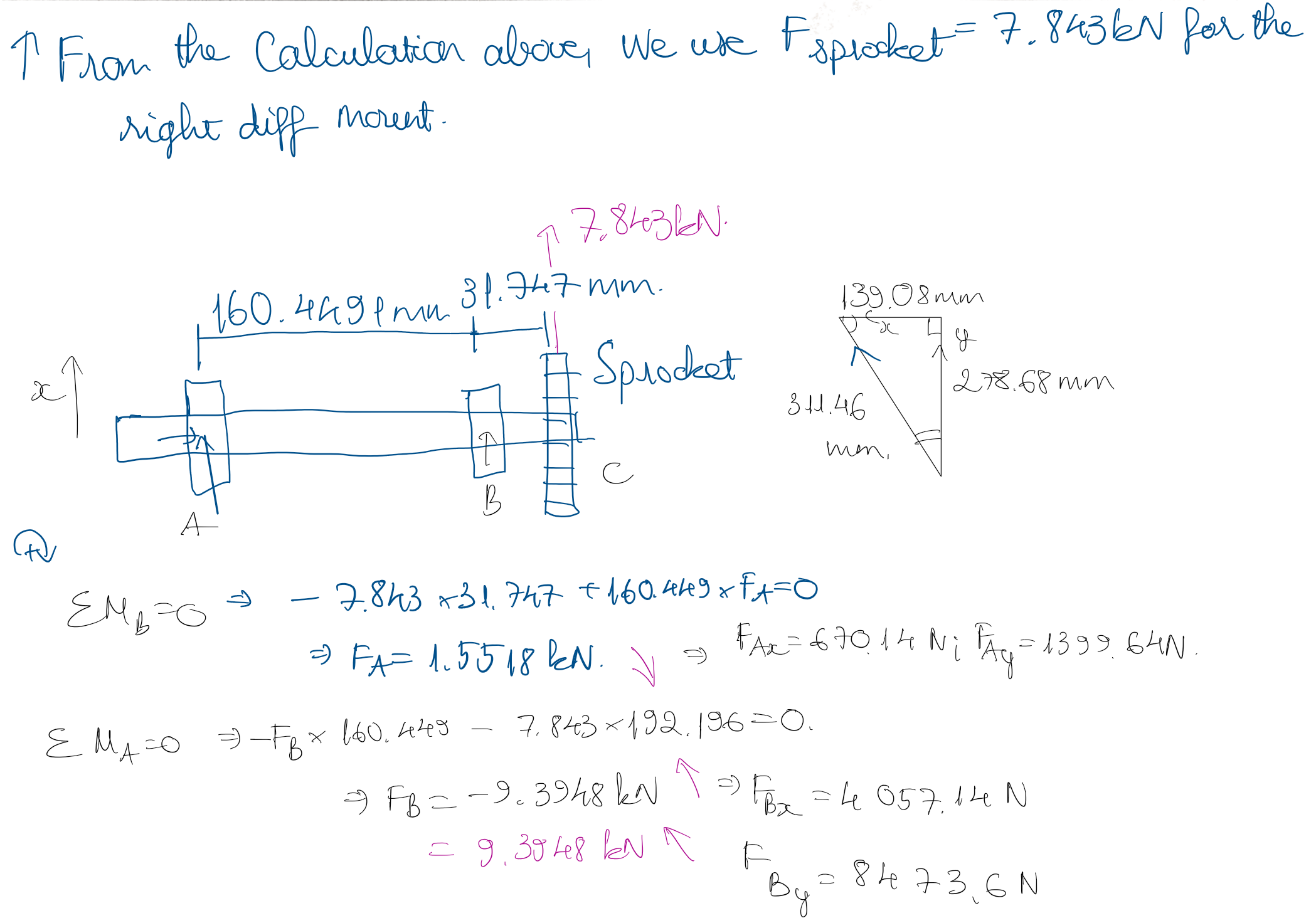
Free Body Diagrams (FBD): I idealized the differential assembly as a supported beam to resolve the reaction forces at the bearing locations. Through summing moments and forces, I identified a critical Radial Sprocket Force = 7.843 kN.
Bearing Selection: Using these calculated radial loads, I selected the appropriate ISO bearings (63/28 and 6011 series) to ensure the bearing’s life exceeded the vehicle's race duty cycle of 200 hours.
3. Mechanical Design & Eccentric Tensioning
The primary design challenge was maintaining axle parallelism while allowing for chain stretch adjustment. A static mounting hole would not suffice since chain tension adjustment is needed.
Eccentric Mechanism: I designed a custom eccentric bearing housing interface. By rotating the eccentric rings, the differential center axis moves fore/aft relative to the chassis, allowing for precise chain tensioning without compromising the perpendicularity of the drivetrain.
Topology Optimization: The mount geometry was iterated 5+ times. I focused on removing material from the "web" sections of the mount (neutral axis) while reinforcing the load paths between the bearing race and the chassis mounting points (clevises).
Geometric Dimensioning: Calculated precise hole distances and tolerances to ensure the eccentric mechanism would not bind under thermal expansion or chassis flex.
4. Finite Element Analysis (FEA) Validation
To validate the geometry, I imported the calculated loads into ANSYS Mechanical for a Static Structural analysis.
Boundary Conditions: I applied the 7.84 kN radial load distributed across the bearing surfaces and fixed the mounting clevises to simulate the chassis attachment.
Stress Analysis: The simulation predicted a peak Von Mises stress well below the yield strength of the aluminum alloy.
Safety Factor: The final design achieved a Factor of Safety (FOS) of 2.9. While this indicates the part is robust, this margin was intentional to account for dynamic shock loading (e.g., hard launches or gear shifts) that static analysis might not fully capture.


Deformation and reaction forces of the left mount.


The right mount has 6 times the load of the left mount, thus experiencing higher stress and reaction forces
5. Integration into chassis
Data Handoff: I extracted the reaction forces at the top and bottom clevises ( ≈7000 N) from my simulation.
Chassis Validation: I provided this data to the Chassis Lead, allowing them to replace "dummy loads" with high-fidelity reaction forces for their full-frame torsional rigidity simulations.